Monday, September 27, 2010

Final results for the Shapeways part

And just to prove that I'm not just making up stories about repairing hundred-year-old furniture for the page hits, here's a picture of the repaired table, with the fixed caster in the center.

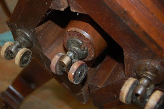
The table has a pedestal base that splits in the middle; each side of the base has three casters, and a central post with a caster supports the table when it's pulled out to its largest size. Here, you can see two of the original casters as well one the repaired one.

My wife mentioned this weekend that she'd always been really frustrated by the broken caster, but never had the stamina to complain to the refinisher and get him to find a replacement of the correct size. She was ecstatic that we could fix the table, and even happier that we'd learned some new techniques to make the replacement part.

Once again, thanks to Shapeways for the replacement part, and Makerbot for making me trust that I could make a correctly-sized replacement part!

Saturday, September 25, 2010

...Wherein the Author Repairs a Hundred-Year-Old Caster...

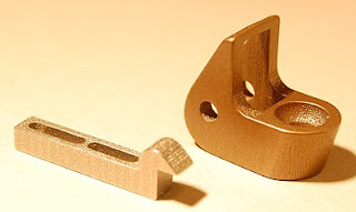
Man, that Shapeways stainless steel is pretty.

I got my second delivery from Shapeways today, and it had the two metal parts: the screen door catch cast in stainless steel, and the dining room table caster printed in stainless but with a bronze finish. Both are well-finished, precise, and smooth - although the photo might make it look like the parts have print lines, the parts actually feel smooth. The larger latch piece is 1.5 inches long, so that'll give you a sense of how fine the metal 3d printing can be.

First step: reassemble the table caster. The part's pretty much perfectly finished straight from the box, but I sized the axle hole a bit small so I could drill it to the diameter of the axle. I was a bit worried about this; stainless steel is usually a horrible material to drill or machine because the metal at the surface hardens as it's cut; if I cut the stainless steel evenly removing a bit each time the drill spins, it'll drill fine, but if I don't advance the drill bit far enough, the metal will harden because of the pressure of the tool, the tool will stop cutting, and I'll have to push lots harder to drill through the casting. Traditionally, this is described as a weird "ka-thunk!" with the drill not cutting, then suddenly grabbing on the metal when enough pressure's added to cut the metal.

Luckily, the Shapeways sintered metal cut drilled smoothly and easily, so getting the axle hole square and the right diameter wasn't hard.

The original axle (only a hundred years old!) was bent, so I knew I needed a new one. The old one had both ends of the rod hammered wide to hold the wheels on, meaning that the caster couldn't be disassembled without cutting the axle. Instead, I wanted to make sure I could remove the axle if I needed to disassemble the caster. Because the wooden wheels are 100 years old (and already have flat spots), I suspect I'll need to replace those some day. For the replacement axle, I borrowed a 3/16" diameter stainless steel pin intended for trailer hitches; one end already had a wide head, and I shortened the pin with my trusty hack saw and cut a slot with my lathe for an E-ring to secure the wheels on the axle using a parting tool. I then drilled out the axle hole just larger than the axle. The axle got reassembled - pin, wheel, printed part, wheel, and E-ring - and out broken hundred year old caster is ready to go back onto the table.

Pics of the fixed table later.

The caster broke when we refinished the dining room table a few years ago. The guy doing the work was apologetic, and searched for a matching caster without much luck. I remember thinking at the time that I could probably machine a new part, but I knew it would be a challenge to get the dimensions right and get the work suitably precise. I'd even thought at the time I ought to learn about bronze casting, but really didn't need an excuse for another hobby.

Fast forward three years, and access to the Makerbot and Shapeways made replacing the part easy. Without the Makerbot, I wouldn't have been able to experiment with shapes and test that the printed piece would fit and function correctly. Without Shapeways, I wouldn't have been able to print the new part in a material strong enough to hold up the table. Without both - a handy, personal 3d printer, and a way to print in exotic materials, we'd still have a broken table.

Thanks, Makerbot and Shapeways!

Wednesday, September 22, 2010

First Shapeways Part!

I got a delivery from Shapeways today - a nice box shipped all the way from the Netherlands to California and containing only the tiny screen door latch. The metal parts must still be in process.
The new part is coated in a matte black finish and feels very light; with the rough finish, it feels almost like dense foam. It's a bit lighter than the original injection-molded piece and Makerbot-made piece. I worried a bit about the part's strength (I printed it in Shapeways's "black, strong, flexible" plastic), but it seems robust enough to be handled when locking the screen door. The bit of white visible on the part shows the underlying plastic color; I used a countersink to cut the depression for the flathead screw attaching it to the door.

The great news is that the Shapeways part exactly matches the original, broken latch in overall dimensions. Although a bit pricey at $6.88, it required none of the sanding and finishing I've done for my Makerbot-printed parts.

The three-latch picture shows how the part compares to the original latch and to my Makerbot-printed part. One surprising difference is in wall thickness. I'd designed the original model to print on the Makerbot, and to simplify printing, I sized all the walls 0.74 mm (or the thickness of two extrusions.) By doing so, the Makerbot didn't try filling between the extrusions and fouling on extra plastic. The Makerbot-printed walls end up at about 1.4 mm, close to the thickness of the original parts. By contrast, the Shapeways part walls came out exactly 0.7 mm thick - half as thick as the original. It looks strong enough, but the part seems surprisingly thin.

Now, I just need to wait for the metal parts to arrive!

Wednesday, September 8, 2010

Differences between Models for Makerbot and Shapeways

I just sent my first parts off to Shapeways - a couple replacement pieces for our sliding doors, and the replacement casting for the dining room table caster. As productive as the Makerbot is, using an outside printing service works for these items. Two of the parts (the caster and a catch for a screen door) need to be printed in metal for strength. The third, a latch for our screen door, will be printed in black plastic. I'm curious how the latch prints; I've been able to print lots of these latches on my Makerbot, but the part requires a lot of sanding to make it as smooth and shiny as the original. I'm looking forward to seeing how the Shapeways's final product looks.

I'll post details once the parts come in.

I was a bit surprised at the changes needed to get a part ready for Shapeways. Take, for example, the latch. When I'd originally modelled this part, I'd drawn it in SketchUp as a solid object. To print it on the Makerbot, I run it through Skeinforge to generate the gcode file which describes exactly where plastic gets extruded. One of Skeinforge's neat tricks is to let the user decide how solid the object should be. Should it be 100% plastic all the way through, or just contain a cross-hatch which provides enough support for the object, but only fills 20 or 30% of the model with plastic? That decision both speeds up printing and cuts the amount of plastic being used. That cost isn't a big deal because the Makerbot plastic costs around $50 for five pounds, or around 10 cents a cubic centimeter.

[Four versions of the sliding door latch. Clockwise from left: original Arcadia screen door latch, injection molded in black plastic. Original model, drawn as a solid. New model, designed to be hollow for cheaper printing. Partially sanded latch almost ready to be used.]

Shapeways, by contrast, assumes that you want the object completely solid unless you design in hollow areas. Their price is also higher because of the better quality printing, the cost of the machines used, and postage. For plastic models, the cost of an object varies from $1.50 to $3.00 per cubic centimeter for plastic and nylon materials, and $10 per cubic centimeter for the sintered stainless steel models. So when I uploaded my original Makerbot-friendly design to Shapeways and asked for a quote for the object, I got a price of $5.63 for the 2.57 cc object, printed in the "White, Strong and Flexible" material.

Ok, time for a bit of thought. I'm a bit cheap, and almost $6 for the latch is on the edge of my tolerance. All that solid material didn't seem essential for the part - were there ways I could cut down on the plastic used? I looked at the original part, and saw I'd made my model a bit too large, so I cut down the shape a bit to match the original, and brought the price down to $4.79 for 2.19 cc of material.

But could I do better? The original injection-molded plastic casting, although cracked, was still around, and I saw that it was actually hollow. Injection-molded pieces pretty much have to be hollow, from what I understand. The plastic needs to cool as quickly as possible after being placed in the mold, and needs to cool evenly to avoid warping. I tried hollowing out my original piece, but found matching the non-right-angles with SketchUp's extrusion tool worked really poorly.

Instead, I started my design from scratch again, this time planning on hollow walls that were 0.7mm or 1.4 mm thick. Those numbers were chosen so I could make test prints on the Makerbot easily; 0.7 mm walls get built as a double shell of plastic filament, and 1.4 mm walls get built as four-thread shells. I extruded side-to-side to get the non-right-angle on the base, then filled in as appropriate to get support for the metal tab that actually moved the latch. It took me a few more hours, but I finally got the piece down to 1.62 cc and a final price of $3.93. I printed a couple on the Makerbot; the pieces are a bit rough, but definitely usable. I'll be interested to see how the final Shapeways parts work.

My other big lesson was why I like the idea of 3d printing complex shapes. The third model, the screen door catch, is a relatively simple design that can be fabricated with machining tools pretty quickly. The version pictured took me a good three hours of careful work (including tweaking the design when it didn't actually fit the existing screw holes). Unfortunately, one wrong turn could have ruined the piece. That three hours of work was also fine for a single model, but I'd hate to have to make three or four of those catches. Being able to make a single model and then print a bunch of parts is much more appealing appealing.

So, my key lessons for the last week:

* It's fun to have access to Shapeways to print final models. I'm looking forward to seeing the final parts.

* Different designs are needed for the cheap-and-Skeinforgeable models for the Makerbot, and the expensive-and-solid models for Shapeways. Sometimes the same model can be used in both places, but plan on a bit of tuning.

* It's often better to start the design again from scratch rather than try to tweak an existing solid Makerbot model because of the difficulty of changing faces inside the SketchUp model. I did have better luck when I switched SketchUp to show a wireframe, rather than solid, object.

* Even when I can machine a part out of metal, I don't think I'd want to make more than one or two of the same part. 3d printing in metal gives me an easy way to make duplicate parts.
Wednesday, September 1, 2010

It's Different When the Printer's Always There

There's always the decision of whether to buy some complex tool like a 3d printer, or just borrow time on one.  When I was thinking of getting a Makerbot, some friends in LA reminded me they sell high end 3d printers, and if I could send them an STL file, they'd be glad to print my part on the nice machine in their garage.  I've never taken them up on that offer. As I've seen when borrowing time on a metalworking lathe, having to *go* somewhere or wait for the opportunity to use a tool increases the chance I'll never do it. Having access to the machine at home makes it much easier to experiment in some spare moments, and try crazy ideas without the planning and commitment to go elsewhere to do my project.

I got reminded of the benefits of having a machine handy this week.  I've been running low on projects for the Makerbot lately.  Luckily, a friend sent a pointer about Jay Leno's  use of 3d printers to keep his classic cars running.  He'll design a part, print it, and if it fits correctly get a copy made in metal, or sometimes use the actual plastic piece when appropriate.

That reminded me of one of my lingering repair jobs.  Our dining room table dates back a few generations (and supposedly came around the Horn to California), but when we refinished it a few years back, the woodworkers broke one of the casters.  It's an odd design - finding the patent is easier than finding a modern reproduction - and the small (1" cube) bronze casting wasn't easily reproduced.  I think I could machine a replacement piece, but I know it would take a few hours work to make a piece, and I'd probably have to redo the piece a few times if it didn't fit perfectly.

Luckily, Shapeways is printing stainless steel these days at $10/cubic centimeter, so I realized if I could make an STL model of the piece on my Makerbot and test that it's the right shape, I could send it off and get a replacement piece.  Our table would then be ready for another hundred years of use.

The problem is that I wouldn't trust that I could get the design of the piece right on the first try... or tenth try, and I certainly wouldn't try making a replacement piece with a three week turnaround time and $40 charge each time. But I've got a Makerbot, and while it won't print in metal and might not be as precise as the expensive machines, I know it's available, and I can easily run through multiple design attempts in an evening. If the design works, then I might send it off to be printed.

So with a couple evenings of work in SketchUp and on the Makerbot, I'd printed four example pieces, found cases where my measurements were off, and tuned the design.

Helpful hints when trying to replace a mechanical piece:

1) The original piece was a bronze casting, and whoever made the original master had worked to make a beautiful piece: smooth curved shape, no sharp edges.  SketchUp, with a bit of work, can add such curves.  However, once the shape stops being a simple rectangle, it's really painful to adjust the position of axle holes and precise measurements.  As in machining, I learned to start by making a very simple shape, add the high-accuracy features, print a model, and test whether it fits and works mechanically.  Once the shape works, then I started playing with the design.

2) By hand, the easiest way to add curves to a SketchUp design is to draw a curve on a flat face, then extrude (or un-extrude) the shape through.  This only allows curves on one face since extruding doesn't work so well with curved faces or angled faces.  SketchUp also doesn't find intersections between curved faces automatically, so extruding (for example) a pair of intersecting holes through an object doesn't correctly handle the intersection.

The Rounded Corners SketchUp plugin might have helped here by letting me round or slope edges to better match the appearance of the original casting.  Note that the Makerbot renders 0.3mm thick levels, so having more than 3 faces on a rounded corner with radius 1mm wouldn't get me a better surface.

The Rounded Corners plugin only works well if I did all edges at the same time, and unfortunately it kept trying to round the drilled holes. I finally gave up, and used the grab tool to manipulate edges to round off the design.

3) I still need to figure out how to do the cupped socket in the casting.  I made the socket here using the "Follow Me" tool, but I'm also tempted to just get the 3d printed metal piece close, then machine the part with a ball-end mill to the precise dimensions.  Machining stainless steel isn't easy, but it might be easier than trying to get a smooth cupped surface at the correct dimension in the STL only.

Now I just need to get my courage up and ask Shapeways to print me a copy in metal. Heck, maybe one of the strong plastics would be enough to get the caster rolling again!

(BTW, Shapeways's price for this piece in stainless steel is $40 - probably worth it so I don't have to machine an equivalent piece. Interestingly, I'd thought their price was based on material used, but it looks like it's actually based on object volume. Because the casting measures in at 4.06 cc, I ought to see if I can get rid of that last 0.06 cc to drop the price $10.) (Bzzt. Ignore Robert's predictions about cost on his late night posts.)

Sunday, July 18, 2010

Two Makerbot Side Notes

1) Tricking out a Makerbot is insanely easy. Cold cathode lights intended for lighting PC cases are dirt cheap ($6 at Fry's), and the 10 inch tube lights fit neatly in the Makerbot case. They were too long to fit in the build area, so I drilled holes in the panel between the build chamber and power supply, and stuck the lamps up into the build chamber as far as they'd go. I used blue and white lights because that's what's available, and they both trick out the Makerbot nicely and provide some decent light to see the model being built.

2) I had a lot of problems getting my Mac laptop configured correctly for printing to the Makerbot. Part of that's my own fault; that laptop has been used with three devices expecting a USB->serial converter. I use the JMRI model railroad software to configure the decoders in my model railroad locomotives. I've installed USB->serial drivers to get a Cricut computer-controlled paper cutter working. Finally, I've got the Makerbot and its serial interface. Most of my problems were caused by JMRI expecting the various Java libraries for controlling serial ports to be installed with the default Java installation on Mac OS X, but both ReplicatorG and the Cricut software ties the drivers to the Mac application.

So this weekend, when I needed to get the JMRI software running, I found the Makerbot configuration was somehow messing things up. I finally got it working after deleting all the various serial port jars and jnilib files from different directories, but kept having problems until I finally got rid of a Java jar file in some directory that I'd renamed from "RXTXcomm.jar" to "RXTXcomm.jar.unused". It looks like Java ignores the file extension, and if there's a file that looks like a Jar file, Java will read it in. Next time, I move all the unneeded files well out of the way.

Tuning the Mendel, and comparing it to Makerbot

"Two three-dee printers? You don't think he's planning on breeding them, do you?"

Sorry, I've been waiting a long time to be able to use that punch line; I'd seen it on a for-sale ad for a maligned Sequent mainframe that had one taker from a university that already had one of the beasts, and the idea that someone *wanted* two of them really frightened the seller. But it's true - I've now got two working three-dee printers in the house. Luckily, they're not breeding, as we're cramped for space as it is.

The Mendel's running, and it's printed some useful stuff. It's still not perfect; model heights are still too short, and there's no place for the power supply. But it's been an interesting experience getting it running, and it's been interesting for me to compare the Makerbot and Mendel experience.

First, details of what I've done with the Mendel. First, like the Makerbot, I'm using 0.5 inch plexiglass for the build surface; I find the ABS sticks well to this cold as long as it's clean, and the completed prints come off decently with a putty knive or chisel. I'm using the Mendel without a heated build platform, and my 6 inch wheel I tried last weekend did warp pretty quickly. I'll have to try some anti-warping tricks (like the lattice base on the Brio track model on thingiverse) if I want to build larger models.

I'm also using standard Makerbot electronics for compatibility with my Makerbot. One annoyance is that the Mendel is intended to be driven from an external single-voltage power supply, but the Makerbot electronics come standard with a 20 pin PC motherboard plug. The Makerbot has that nice box to hide the power supply, but the Mendel has no place to hide the power supply. For now, it sits to the side of the Mendel.

It's hard to adjust the Z axis height on the Mendel; on the Makerbot, I'm used to tweaking the Z axis pulleys or belt to adjust the printhead height. A Z axis knob (like this) is a necessity.

That brings me to philosophy. Getting the Mendel running has been a fun experience; it's freeing to know that I can basically build and tweak all the different parts of a printer (including making a new extruder based on the Makerbot parts, and figuring out how to get it to fit in the existing Mendel). I'd realized when building the Makerbot that there's nothing particularly sophisticated about the mechanism for the 3d printer; all the magic really is in the software that figures out where to move the extruder, and how fast to move it. Beyond that, the mechanism is pretty simple, with reliability being the only big concern.

But building the Mendel also pointed out that while the mechanism is easy, there were all sorts of design tradeoffs that the Makerbot team made. The smaller print surface makes for a nice enclosed box design and minimizes the problems with warping. The enclosed box style provides a place to hide a standard and cheap power supply. The placement of the power supply and various Makerbot circuit boards seems easy, but when I had to figure out placement and wire length constraints when assembling the Mendel, I realized someone had to think hard and long about how to arrange the Makerbot, and where to run wires, and how to avoid boards getting in the way of the mechanism. The design of the Z axis makes it really easy to move the printhead large distances, moving it up when disassembling the print head or trying to get things set up, and moving it quickly down to build surface height to start a build. Makerbot's removable build surface simplifies getting a putty knife under a sticky print, but with Mendel, I need to be careful the build platform doesn't move as I pry.

Someone had to think of all those little details on the Makerbot, and they did a pretty good job. I'm happy I've built my Mendel, but I think the Makerbot's still going to get more of the work just because it's easier to put on top of the bench, and easier to adjust.

Friday, May 28, 2010

Next Project?

So the Mendel printer's almost done. What's on my list of potential projects?


  • Build a model of a railroad handcar, using the Makerbot to print all the cast and fabricated metal parts, but using wood for the parts that would be wood on the real thing.
  • Print some large railroad wheels, either for the handcar or for some other project. How large can I go?
  • An HO model of a 1950's style burger stand (like this Dairy Queen
  • More ergonomic throttle case for the model railroad throttles I use.
  • Print a full railroad car in HO. (Requires the Mendel so I can print a 6" long piece.)

RepRap Mendel Printing!

Once I'd printed all the parts for my Reprap Mendel printer, I thought I was close to done. In reality, it took me another two months to finish: getting the stepper motors, tuning the mechanism, and (finally) making a new extruder for squirting out the plastic. The last step was the hardest; the Makerbot plastruder won't fit on the Mendel, and the new heater barrel needs to be longer than the Makerbot one.

After a bunch of assembling, machining, and cursing, I finally had my Mendel printing tonight. The X axis is still slipping a bit and I'm having problems with dimensions (probably because of friction on the X carriage), but I printed several of the 20 mm test cubes in a row, so it looks like the Mendel's printing.

Woohoo!

Details:


For the Mendel itself, it's mostly built as described in the instructions, but I did make two changes. I was going to use the Mendel's long drive gears for the stepper motors, but filing flats on the stepper motor shafts was too time-consuming. I instead went to nophead's Mendel pulleys, drilling each to be a press fit on the stepper motor shaft. So far, they've worked fine with no slipping. Each required a little cleanup with a grinding bit in a Dremel moto-tool to clean up extra plastic on the gear teeth. I also ended up fabricating the X axis motor bracket from sheet plastic (1/2" thick) because of problems printing the part.

For the extruder, I used Zaggo's Printruder II with a Makerbot gear motor, homemade printer barrel, and homemade gear pulley. I turned the pulley from brass rod on a lathe, cut the teeth with a file, and drilled and tapped a hole for a set screw. The teeth weren't large enough to grip the filament at first, but some coarse filing resulted in ugly, but very functional teeth. I used a spare Makerbot heater barrel and a new insulator barrel turned from PEEK rod for the heater. The insulator barrel needed to be two inches long (as compared to 35 mm/1.3 inches) to reach through the Mendel's X carriage. Turning the PEEK was remarkably easy; it machines easily and doesn't melt too quickly. It's also expensive at $30/foot, but I much prefer being able to make my own insulators whenever my Makerbot breaks. I couldn't find screws long enough to reach from the heat shield to the printruder body, so I took more brass rod, drilled and threaded it through, and the used two 1.5 inch 4-40 screws to hold the heat shield and pull the barrel to the printruder body.

I've only printed so far with the Mendel using the Makerbot's electronics. If it looks like it's printing well, then I'll take the plunge and buy another set of the Makerbot electronics. I had to solder extra-long wires on all the stepper motors and buy new Molex plugs to fit the Makerbot stepper motor drivers. The extruder controller seemed like it wanted to be closer to the Mendel, so I mounted it as shown.

What do I think of the Mendel so far? It's a mixed bag. I'm really pleased I got this running, and that I was able to fabricate many of the parts (heater barrel, extruder gear, etc.) I'm really curious to see how it does at printing large objects. The Mendel's generally quieter than the Makerbot. On the minus side, the Z axis is a lot slower than the Makerbot because of the large gears at the base of the Z screws. It's difficult to get to some parts; removing and reattaching the extruder (at least with a Makerbot-like heat shield) is more work than on the Makerbot. I also missed the Makerbot's exposed Z axis belts, for it makes minor height adjustments when printing the raft easier. It's possible to adjust the height by spinning the Z screw gears, but they're hard to reach and turn.

More as I get some experience with the new printer.

Monday, March 29, 2010

When in Doubt, Build a Mendel

Okay, I don't know why I'm doing it.

I've been having fun with my Makerbot. I've had occasional interesting projects, and occasional uninteresting projects. I've been a little frustrated by the maximum size the Makerbot can handle, but not that frustrated. I also tend to be annoyed at the people who use machine tools only to build handy tools for machining.

But for some reason, when I saw Spacexula's Mendel Production Set, I thought, "Hey, that'll be fun, let's try printing parts to build another 3d printer!"

Now, to be fair, I was interested in how he'd packed several parts onto each print. When all my Makerbot prints have been 45 minute waits for a single part, it was pretty cool for the first print to give me seven or eight decent parts. From there, I just kept going, slowly filling a shoebox with the completed parts. Then I ordered the various hardware, and... well, now, I've got the mechanism for a Mendel almost done and I'm kind of curious what I'll do with it.


It took about two weeks of printing to get almost all the parts done, with several prints on weekends and (if I was lucky) one or two complete prints during the week. I had remarkably good luck; maybe 60% of the prints worked fine the first time. I had some other problems with prints curling and jamming the print head. Some of the larger parts such as the lower carriage went really badly, with too much plastic at screwholes jamming the printer. I even resorted to using a failed print on the carriage when I couldn't complete a full print.

I assembled the Mendel this weekend after making a big parts order to McMaster and the bearings here. Both shipped immediately and arrived quickly. I still am waiting on the stepper motors (which I'm getting from Alltronics - I'll let ya know how that goes), and once those are running, I'll see how my mechanism works.

Helpful hints for building a Mendel:

  • The Nyloc locknuts are a bear to work with, hard to put on and a pain for disassembly. I ended up falling back to regular M4 nuts for connections that didn't look like they were liable to shake loose. If I do have problems, I'll either add a second nut or a Nyloc nut.
  • The ground steel rod is hardened, and my hacksaw wouldn't scratch it. I ended up using a Dremel moto-tool with a cutoff wheel to cut the hardened outside layer of the bar, then used the hacksaw to cut the bar.
  • I ended up needing to drill out all the screw holes to get the screws in. When screw holes need to line up in parts, I used the machinist trick of drilling out the top piece separately, clamping all parts together, then using the top piece as a jig to keep the holes aligned.

It's also been interesting to compare the Mendel to the Makerbot. If I had to choose Makerbot or Mendel, I'd go for the Makerbot - assembly was quicker, it feels more robust, and various design points just feel better. The plastic bushings and guide rods for the X and Y axis require much less tuning, and the magnetized build platform makes it easy to print, then pull the platform out to scrape the print off the build platform.

The Mendel wasn't that hard to put together, but the printed parts sometimes annoyed me because they weren't as precise as machined or laser-cut parts. The Makerbot went together much better, and feels more robust, while I keep wondering which printed parts will fail first. For places where accuracy matters (such as on the guides for the X axis assembly), a little bit of debris or extra raft material can throw off rod spacing, and makes me think I'll have problems with alignment and friction.

Sunday, March 7, 2010

Well, THAT didn't work!

Definitely no luck with the homebrew heated platform. The 10 ohm nichrome wire pulled about an amp of current (not surprising for a 12 volt power source), but took 10-20 minutes to heart up. I poked a wire into the silicone between the layers of glass and dragged out the middle of the wire, and soldered a new wire on. By connecting the new midpoint to one terminal and the original two wires to the other terminal, that meant I had two wires in the platform that were half as long, and it drew (not surprisingly) 4 amps... and started heating the plastruder circuits too much. (It heated up really fast, though!) I then just connected up one side for 2 amps of power... and the glass quietly cracked.

Next step: two amps of current seemed ok for the plastruder, so if I remake the build platform (and try glass again), I'll try stretching two 10 ohm / 16" nichrome wires inside. The platform can definitely use the extra nichrome to spread out the heat source and hopefully keep the glass safe.

Saturday, March 6, 2010

Heated Build Platform

After seeing some of the great results folks have had with heated build platforms (such as Hydraraptor's groups of pieces, I wanted to try one too. I'm mostly interested in cutting the warping of long parts, avoiding printing rafts, and experimenting with the nichrome wire.

Here's a photo of my build platform; I based it on Hive76's design that they're selling through Makerbot. I far as I could tell, they use a couple pieces of glass, nichrome wire, and silicone sealant to make their build platforms.

I tried the same, though I sealed all the wires between the two layers of glass with tons of silicone. I used the same 10 ohm piece of nichrome, soldered the ends to longer pigtails of copper wire. I then cut two pieces of 4" square glass with a glass cutter and straightedge. I used dots of silicone and carefully placed weights to get the wire in place. I also added a spare thermistor and wires for measuring temperature, then covered everything in silicone, added a spare piece of copper wire at the far side of the platform to keep the pieces of glass parallel (because of the soldered connections on the near side), then smushed the two pieces of glass together.

I also used a bit of Radio Shack pre-drilled circuit board for the circuitry to connect the thermistor to the spare A6 analog port on the extruder controller.

I found 16 inches / 10 ohms of nichrome wire isn't enough to get sufficient heat; it took around 15 minutes to heat the glass to 55 degrees Celsius, and while the ABS would bond to the glass at hotspots above the wires, the plastic wouldn't stick to the glass elsewhere, even if I made sure the glass was clean and free of grease.

Looks like I'll stick with my 1/2" plexiglass build platform I currently use, though I might take another pass at the heated build platform in a few weeks.

Also this weekend: my original extruder nozzle/heater died with a broken wire, so I made a new one from spare parts. The original one put in a fair number of hours. I also found that ReplicatorG version 13 (for the heated platform support) also is much quieter about moving the stepper motors - that was a nice surprise!

Sunday, February 7, 2010

Lessons learned from printing the drain screen

I had to modify the drain screen - the arms weren't long enough to hold it securely. I lengthened the arms of the previous design, printed a new copy, and it's up on the roof - we'll see how it does.

Building these taught me a few lessons about designing parts for the Makerbot:

* SketchUp might not make it easy to add cosmetic curves, but it's really easy to grab particular edges and pull them to get smoother shapes. I extruded one of the sides out an extra 1/8 inch, then moved the top in so the whole face slanted, and got a more interesting design.

* There's a few magic numbers to know about your Makerbot. Smaller (1/16" wide) features often get fabricated with only the two extruded lines along each edge. (The Skeinforge Carve setting "Perimeter Width over Thickness" sets the thickness of the perimeter.) Pieces that are wide enough for four extruded lines will appear solid; pieces that are 4.5 lines wide will have a hollow in the center. This was a big deal when I was printing the HO model strip mall parts because I needed the face of each part to be smooth.

Building smaller features with perimiter lines only was a good thing for the drain screen; the spanning horizontal pieces were sized 1/16" wide so the extruder bridged the gap quite well. When I widened the face, the edges of the bridge were fine, but all the fill between the lines just fell out because there was no support below.

* Printed parts are stronger in the x/y direction than in the Z direction. I had problems with adhesion between layers for parts that took stress (such as the drain arms.) Printing these separately and flat might be a better idea. I also had adhesion layers in the vertical sections, probably because the horizontal strands bridging the gaps would pull on both the pieces supporting it. I don't have a good solution for this.

* I did try building a piece with unneeded solid connections between the legs to cut the amount of loose filaments. This worked well, but probably isn't good for keeping the drain clear.

Saturday, February 6, 2010

Making Practical Things

Our flat-roofed 1960's modernist tract house may have really cool lines, but it requires a bit more maintenance than a normal house. Leaves and other debris fall on the roof and clog the downspouts, resulting in cold and annoying maintenance as well as potential long-term problems. It doesn't help that the tree that shades the house and keeps us cool in the summer drops nasty, sharp seed pods that are almost the same size as the drain openings.

Unfortunately, our drains aren't standard - the openings are a bit less than two inches wide, which means those seed pods can block a downspot and give us a miniature lake on our roof. Much of the drain hardware we find at the store either is intended for commercial buildings, or for the typical gutters that most houses use, so I've never found a good solution for keeping the drains clear. I'd found some wire "baskets" that fit in the drain opening, but these were designed for 3 inch openings, so I'd spend an hour of work unweaving them to fit a smaller opening.

Luckily, I've now got a Makerbot, so as long as I could design a basket, I could protect the drains. These two drain screens have prongs which fit into the drain pipe to hold it in place, but otherwise sit flush against the roof. I designed the openings so they were smaller than the round seed pods from the Liquidambar tree. I'm assuming they'll also keep the leaves out, but let some of the smaller debris into the drainpipe and away from the house.

This is the most practical use of the Makerbot I've found so far. I haven't been able to find suitable drain screens commercially, but I've got a reasonable idea of what will work. I also need multiple pieces; Makerbot sometimes seems like a lot of work for a one-off piece, but if I need duplicates, it's great!

On the negative side, I'm not sure how the white/natural styrene is going to survive life on the roof. I've had problems with white styrene sheet warping from direct sunlight, and the roof's liable to be hotter than any place I normally use styrene. Painting might help (or I could just buy the black styrene rod on the assumption the black pigment will ward off the UV.) We'll see how it does.

I designed these over a few hours in SketchUp. Each is 3.5 inches across and 1 inch high, with the drain arms being 2.75 inches tall. Each drain screen prints
upside down with the flat top printed first. The arms that press against the sides of the drain are springy enough to fit in a slightly smaller hole. Note how horizontal pieces bridge space; even without support material, the extruded plastic will cool and tighten horizontally to bridge short (1 inch) gaps. Each piece took around 90 minutes to print. As usual, objects printed flat have great detail and sharp edges. The multiple small outlines for each of the legs prints less nice, and the extruder's jumps between legs left a lot of filaments and rough edges on each vertical piece. If I were doing this again, I might try to have wider or connected legs so that the extruder can extrude several areas on one path. I also considered printing the drain arms separately and flat so they printed cleaner, then attaching them to the main assembly with a snap-fit. I decided in the end it wasn't worth the trouble; maybe I'll do that on my next project.

I'd originally planned these to be round and have interesting curved lines, but SketchUp's extruder tool works better on flat faces than on curved faces. I'm also disappointed that adding in cosmetic curves in SketchUp isn't so easy. Gratuitous curves might not be needed for function, but printing curves in Makerbot is so easy that I feel guilty if I don't add some in.

If these two fit the openings on the roof when I test tomorrow, I'll print several more for the rest of the downspouts. They're also the largest things I've successfully print, so I'm feeling like this has already been a successful project.

Both printed pieces had problems when I was doing cleanup. On the first, the slimmer arms broke, and on the second, part of one side delaminated. Superglue works great for repairs; liquid cement (aka MEK and acetone) doesn't seem to melt the extruded plastic as well as it melts regular styrene sheet, though it'll eventually soften and weld the break.

Sunday, January 3, 2010

There's a Skeinforge Setting for That...

I'll share a couple bits of wisdom from trying to do a 3d print of a HO scale model building. (BTW, the prettier pictures are here.)

Keith's Electronics Blog reminded me that if there's a printing problem, there's usually a Skeinforge setting to fix it. The picture shows the front face for the store. I've inset this behind my nice arches, so I didn't think it would be as visible as the main building facade. So, I tried seeing whether I could print an adequate building part without spending a couple hours on gesso, spackle, or other fillers.

The top blank shows the initial attempt. Note the diagonal striping from the fill, and also note that it has a strong washboard texture. This doesn't look so hot (even from a distance), and if I was seriously building this model, I'd be scratchbuilding the building face from plastic strip.

The diagonal stripes are the worst part, but I remembered that Skeinforge has a setting to specify the fill pattern - the angle of the initial fill lines, and the amount to rotate the fill on each layer. Making the stripes either vertical or horizontal would help make the piece look more realistic, because then it might be passed off as the outlines of wood. I tried changing the initial fill angle to 0 (then to 90 degrees when I realized the stripes came out horizontally.) The vertical strips look better; they might be wood detail, but the curves at the end of each fill pass spoil the illusion.

On the third one, I made two changes: first, Keith's blog suggested playing with the Carve setting's "Extrusion Width over Thickness". This controls the thickness of each layer, and determines how much the stream of plastic get squished into place. By changing this value from 1.9 to 1.5, the occasional gaps between the extruded plastic disappears, and the surface starts looking more like a flat surface with board texture. Second, I added some "trim pieces" to the top and bottom to cover where the fill path curved back. This final piece looks much more realistic (except that the "trim" over the window has a gap because it's 4.5 extrusions wide; reducing that size a bit would get rid of that gap.

The third building face still isn't suitable for close-up viewing, but it looks decent at a distance and in shadow. With this print, I'm starting to believe I could use the Makerbot to build HO buildings.

Friday, January 1, 2010

Now it's getting hard to figure out where to put the entries. The post had more on the model, so check my railroad blog for details on printing a model of a 1920's drive-in market, and more photos of my progress.